|
|



|
|
|


.
Above All, there is the "L"!:
The Structure Adapts to Changing Conditions
By Stan Kaderbek and Art Peterson
All photos from the Krambles-Peterson Archive
|
|
|
|
|
.
Above All, there is the "L"!:
The Structure Adapts to Changing Conditions
By Stan Kaderbek and Art Peterson
All photos from the Krambles-Peterson Archive
Within the first decade of its existence, the "L" structure had to adapt to changing conditions around it. This is a process that has extended to the current day. The built environment, of which the "L" is a part, is always evolving. Fortunately, the designers of the original "L" structure included a robust safety factor in their calculations, meaning that changes in rolling stock (car weights would steadily increase through the 4251-class cars of the 1920s, as well as the North Shore and CA&E cars of that era) were within the structure's capabilities. This installment considers some of the changes that the structure has had to go through over the years, presenting them in the order in which they appeared on the scene.
Bigger Streetcars Resulted in Numerous Column Relocations
During 1907, the Board of Supervising Engineers (BOSE) -- a regulatory body responsible for overseeing the rehabilitation, modernization, and operation of Chicago's street railway system between 1907 and the 1940s -- established the design parameters for the cars with which the operating companies holding streetcar franchises in the city would have to conform.
Chicago City Railway's 1906-08 400 car order from Brill was one of the designs that met the BOSE's requirements -- a double-truck, pay-as-you-enter (PAYE) type car with enclosed vestibules. These cars were 48'-3" long and 9'-0" wide, 46% longer and 18% wider than the biggest of the double-truck cable cars and many of the streetcars that preceded it. That longer length resulted in a corresponding increase in truck center spacing, which impacted the minimum radius these cars could negotiate. The increased car width further affected the clearances required for these larger cars when making a turning move at an intersection. Those changes in track geometry, as well as the need to provide 10'-2" track centers between connecting tracks at intersections (ensuring at least 6" clearance between passing cars when making a turn) resulted in relocation of "L" columns at several intersections throughout the city.
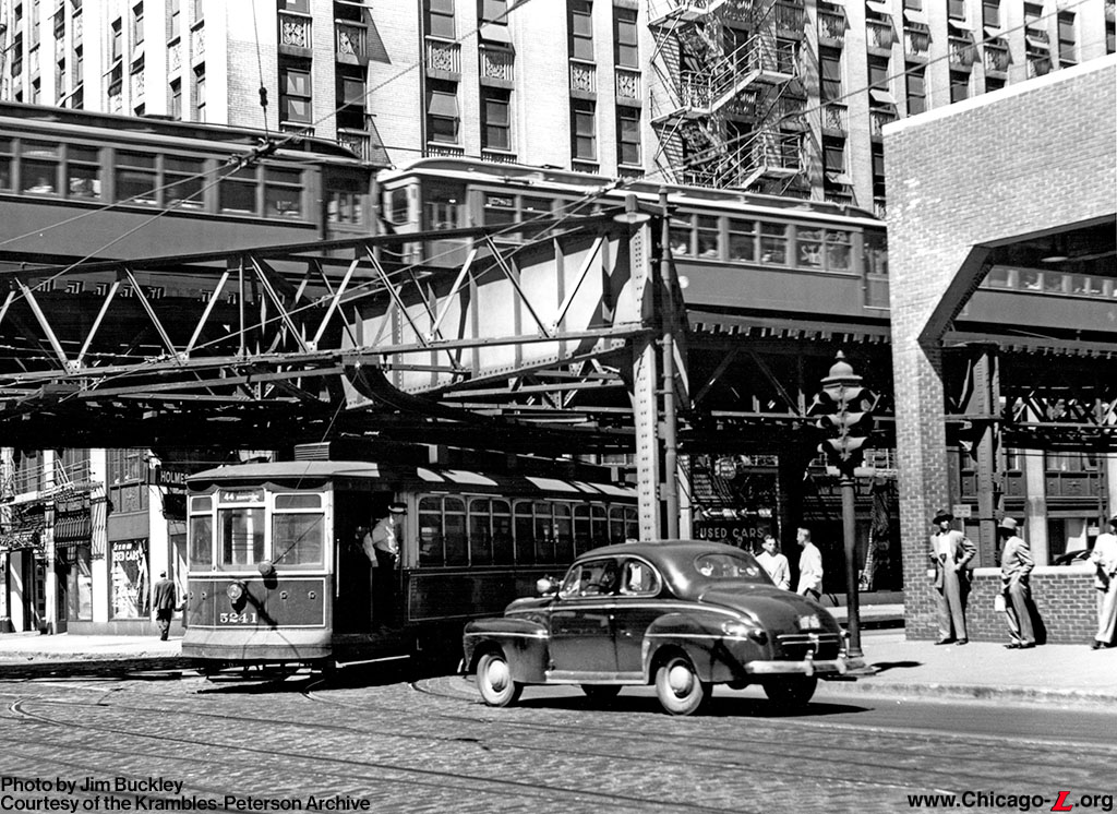
In this view, Jim Buckley caught Chicago Surface Lines car 5241, working a #44 Wallace-Racine run, turning from northbound Dearborn Street onto eastbound Lake Street on May 28, 1949.
Truss Bridge Displaced by Chicago Union Station
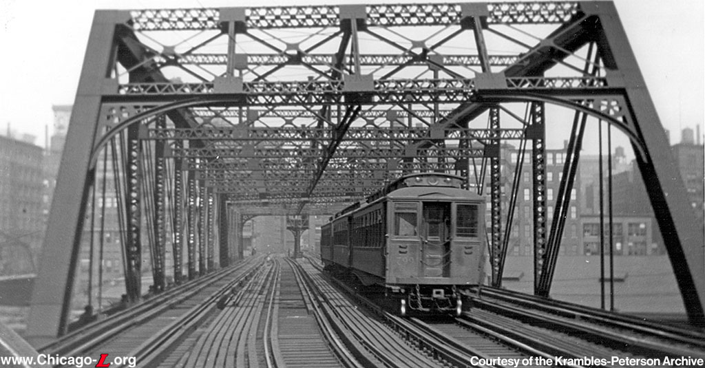
The impressive four-track through truss bridge over the Chicago Union Depot tracks is shown looking east from the Canal Street station. To expedite procurement and to reduce construction expenses, the truss bridges on the "L" were typically pin-connected trusses. An issue with this type of truss bridge is that it is inherently non-redundant, meaning that the loss of one principal member or of a connection will lead to the collapse of the structure.
In the case of the Metropolitan mainline bridge, the massive project to replace the Chicago Union Depot with Chicago Union Station (CUS) made it expedient to replace this bridge with a through-girder structure. Changing track patterns on approach to the station, as well as locations for supporting CUS structures, affected "L" column placement, etc. Site preparation for the CUS project began in 1913. This $75 million effort would take 12 years to complete, thanks to materials restrictions during the First World War.
The Structure Can Take a Lot, but...
Earlier in this piece, we talked about the substantial safety factor that the original designers working for the four "L" companies included in their calculations for design of the original structures. This made it possible for the structure to take a lot of punishment from a variety of sources over the years.
One instance that got the better of the structure was the May 19, 1934 fire at the Chicago Union Stockyards. The fire's main east-west axis ran essentially along the Stockyards "L" line and damaged/destroyed the structure from Emerald Avenue on the east to Morgan Street on the west. In addition, the Halsted station on the branch was destroyed and CRT car 394 (caught just west of the station) was also consumed.
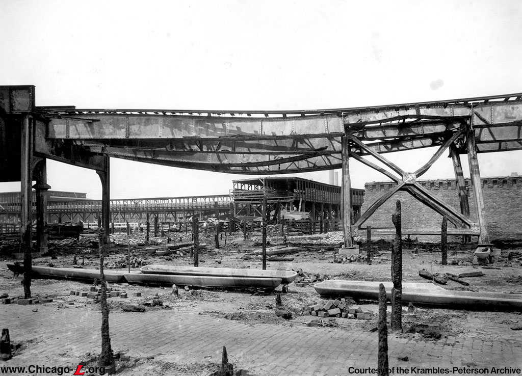
About 80 acres of land were consumed by the fire, which required 2,200 to fight it for over four hours until bringing it under control. Damage due to this fire was estimated at $80 million. Fifty people were injured and one died because of the fire.
The deformation shown in the photo indicates that the temperature of the fire was well above 400 degrees F, more likely around 1,000 degrees F. At 1,000 degrees F (or higher), the yield strength of the steel is reduced by 40% compared to its original yield strength, causing the structure to lose the ability to stand up on its own. When the fire department pours water on the structure this process essentially quenches the steel and changes its microstructure, making it more brittle. Consequently, there was no question about salvaging any part of this damaged structure -- it required replacement before service could be restored.
Responding to the Railroads' Requirements
The mid-1960s was a period of great change in terms of freight car materials, configuration and consequently capacity. The first tri-level auto rack was built by the Frisco during 1960, while the prototype 86-foot long high-cube boxcar was built by ACF in 1963. These car designs were successful, with production orders of both car types appearing throughout the 1960s. Industry-wide adoption of these modern car designs led to changes in the American Railroad Engineering Association's clearance diagram requirements, where the overall car height to be accommodated went from 21'-6" to 23'-6".
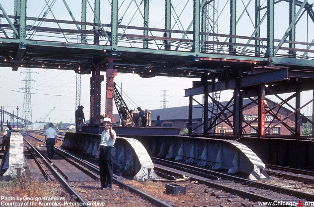
That change in car heights immediately affected a number of the locations where the "L" crossed mainline railroad tracks. In George Krambles's July 16, 1966 photo above, CTA and railroad personnel are engaged in raising the pin-connected truss over the North Western and Pennsy railroads at Rockwell Street on the Lake Street "L".
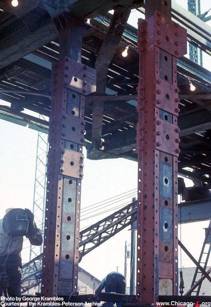
CTA structural engineers developed an ingenious way for quickly raising the profile of the "L" structure. Fondly called the "pogo stick," this was adjustable shoring, which could be easily deployed. George took this close-up view of the pogo sticks in use under the Rockwell truss bridge on July 16, 1966.
Each one consisted of batten plated steel channels with holes for pins to go through the batten on either side. The process for using the sticks consisted of building a timber foundation for the stick to rest upon. Then, the pogo sticks were erected. Next, a jack was placed between the pogo stick and an adjustable steel base that had been installed on the channels. The pogo was then jacked and when properly lined-up, 4" diameter pins were placed in the batten plate holes to secure the new position. The pogo sticks would remain in place once the desired raise of the structure had been achieved.
Expedited Bridge Roll-Out/Roll-In [Replacement]
As noted in the discussion of the Met mainline truss bridge, the inherent non-redundancy of the pin-connected trusses made them a target for replacement. The need to deal quickly with bridges of this design was emphasized by the December 15, 1967 collapse of the chain link suspension Silver Bridge (between Ohio and West Virginia). This accident resulted from a small (undiscernible) crack in an eyebar which grew and led to the bridge's complete failure. As a result, a National Bridge Inspection program was developed. Concern over the ability to absorb the on-going impacts of the inspection requirements led CTA to seek alternatives.
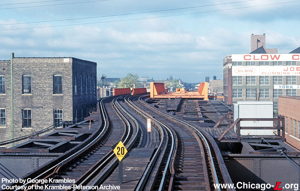
The Rockwell bridge on Lake Street was an early target for replacement. In this instance, a shoo-fly was built, as seen in George Krambles's October 10, 1967 photo above, while the truss bridge was replaced by a through-girder structure.
The overall process of replacing the truss bridge and eliminating the shoo-fly operation took about two years. A shoo-fly is one way to replace a bridge and still maintain service around the work site.
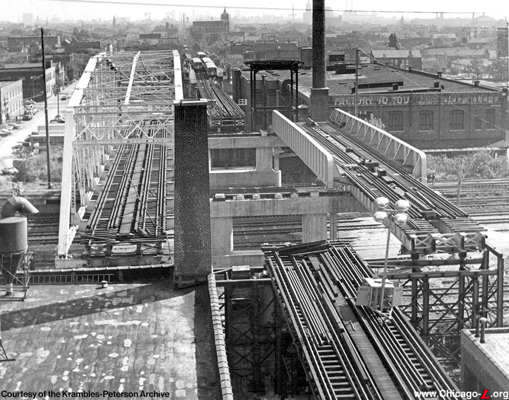
A better method was needed. Ultimately, the CTA looked to the railroads for an answer. The mainline railroads had a significant body of experience with the roll-in/roll-out method of construction. CTA engineers settled on the roll-out/roll-in process for replacement of the pin-connected trusses on the system. In this October 3, 1981 eastward view of the Douglas "L" crossing over the C&NW, looking at the near end of the new structure to go along with the through-girder bridge (right hand side), the steel framework has been erected to support the new structure and facilitate its roll-in. These structures (at either end of the structural replacement zone) also facilitated the roll-out of the truss bridge. The photo also shows the new, intermediate concrete piers to support the new bridge. This bridge replacement project could be accomplished over a weekend (late Friday night to early Monday morning). Sharp-eyed readers will also note several pairs of trains congregating in the Western station, which was the temporary terminal while the bridge work was in progress.
Letting the Structure Win a Few
In the first installment of this series, we talked about the issue of "pumping" column footings and how the deteriorating foundation led to loss of column support and inducement of a twisting motion into the associated cross-girder. This problem became more acute as the South Side and Lake Street structures approached their 100th birthdays. During the late 80s, there was at least one instance where a truck struck a column on Lake Street destroyed a deteriorated column/column base in a "simple" collision.
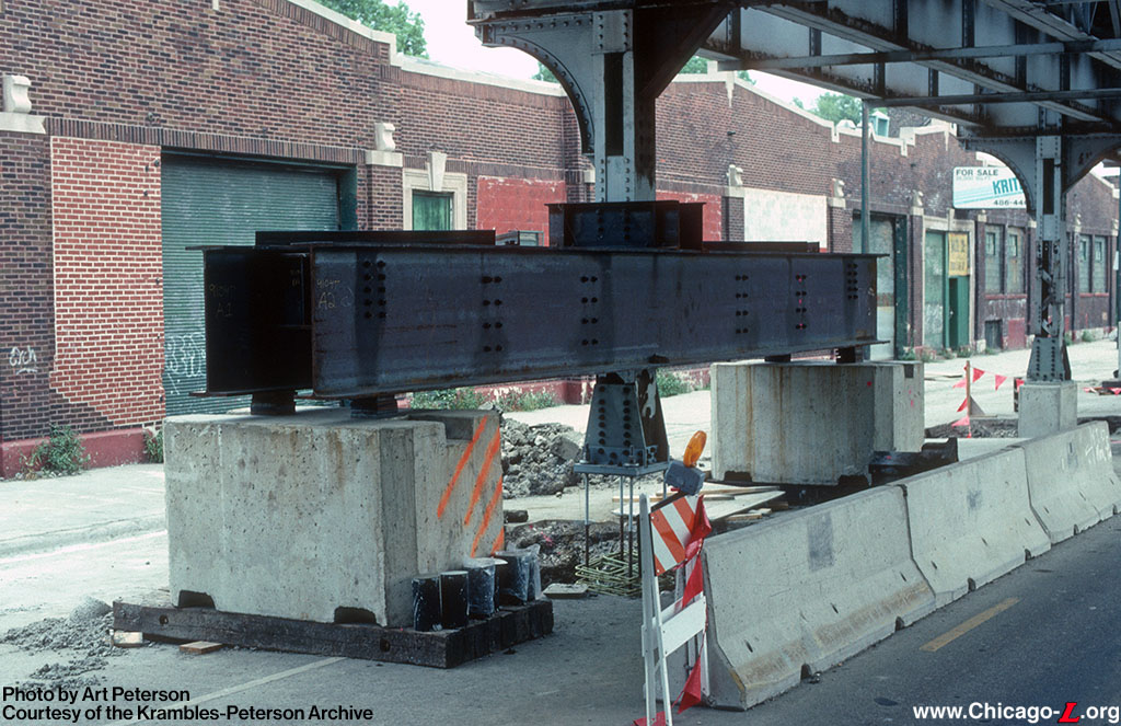
CTA engineers designed a more-robust column base/foundation design, such that the structure wouldn't be left "hanging in the breeze." This July 12, 1991 view near Homan/Lake shows those more substantial column bases in the background. The column closest to the photographer is temporarily supported (as well as being jacked slightly to ensure that the load is transferred to the temporary supports) while a new foundation and base will be constructed.
|
|
|
