|
|



|
|
|


.
Above All, there is the "L"!:
Appreciating its Structure
By Stan Kaderbek and Art Peterson
All photos from the Krambles-Peterson Archive (except as noted)
|
|
|
|
|
.
Above All, there is the "L"!:
Appreciating its Structure
By Stan Kaderbek and Art Peterson
All photos from the Krambles-Peterson Archive (except as noted)
Every fan has their favorite location(s) to view the "L" against the backdrop of the City -- for me, two that come to mind are the view into town from Western/Milwaukee, where the "L" rises over the former Milwaukee Road right-of-way at Bloomingdale Avenue and then there's the view south on LaSalle Street across the Lake Street structure, capped off by the Board of Trade Building.
The "L" is an inseparable part of those views -- without it, Chicago wouldn't be Chicago. Threats to its existence (think of those 1970s proposals to scrap the Loop "L") were cause for extreme concern. The "L" combines elements of style, if not beauty, along with a good dose of engineering history. On top of that, it's a fun ride, unmatched for the experience/vista it offers to its riders.
The Lead-Up to Chicago's "L"
CT Harvey had a single-track elevated line running along Greenwich Street (later extended to 9th Avenue) in New York from July 1, 1868. Cable propulsion was used, and ultimately issues with the reliability and noise associated with the cable would lead to the line being closed by August 1870. The structure consisted of a row of single iron columns beneath the trackway (also referred to as a "one-legged plan"). Harvey's operation was ultimately taken over by the New York Elevated, which converted the line to steam-hauled trains, commencing on April 20, 1871.
A more-typical "portal frame" structure (pairs of iron columns connected by transverse girders, as well as girders running parallel to the roadway) was adopted for the design of the structure used by the Metropolitan Railway, which opened its 6th Avenue line in Manhattan on June 5, 1878. This road used steam propulsion from the start.
Both these operating companies ultimately came under the control of the Manhattan Railway, a holding company, that was established in 1879. Of particular interest to the Chicago story, RI Sloan was Chief Engineer of the Manhattan Railway. He would assume the same position with the South Side Rapid Transit (SSRT). Some of the crews initially working on the SSRT were also ex-Manhattan Railway employees.
It was an era of many competing proposals. One which has relevance for the Chicago "L" was JV Meigs's monorail concept. Originally patented in 1875, a demonstration line was running in East Cambridge, MA from 1886. This concept was considered for application in both Boston and on the Lake Street Elevated (LSE).
As Bruce Moffat noted in CERA Bulletin 131, recognition of the many modifications that would be required to adopt the Meigs system in Chicago led to LSE abandoning plans for this technology in late 1889. The road adopted the more-conventional cross girder (portal frame) structural design developed by Theodore Cooper of New York. Mr. Cooper had a national reputation for the design of railroad and highway bridge design; between 1885 and 1902, Cooper published several important works on railroad and highway bridge design.
An excellent history of the "L" is presented in Bruce Moffat's CERA Bulletin 131. This piece is not intended to rehash that history, but rather to concentrate on the elevated structure itself, noting some of the challenges that have been faced, unique approaches taken, etc.
Chicago's "L" Structure
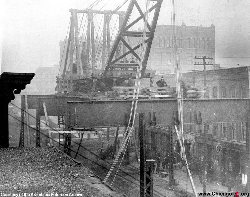
Erection of the LSE structure began near Canal Street on December 18, 1889. This view shows the traveler crane sitting on the completed portal frames, consisting of supporting columns at either end of the transverse girder. Stringers, running parallel to the trackways, are hidden by the angle of this view. The columns rest on footings (foundations), which are under the surface of the sidewalk. As the name implies, the "traveler crane" erects the framework ahead of itself and moves along the completed structure.
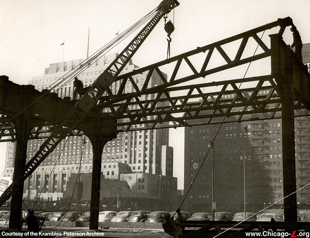
This view shows the stringers which ran parallel to and under the tracks on the Market Street Stub structure of the LSE. This view looks west-southwest near Market and Washington in 1948. Early stringer construction used an open-lattice structure.
This structure went into service from 1893.
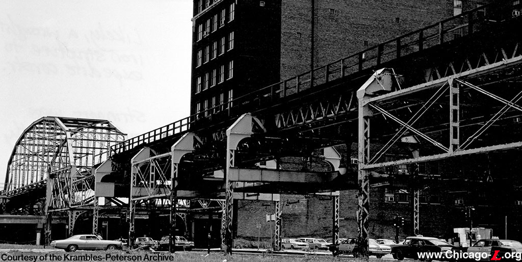
It's the opinion of the authors that the 1892 SSRT structure and that of the LSE (from 1893) were "best iron," also sometimes called "puddle iron or steel". "Puddling" involved pouring hot layers of iron into molds where each new layer of steel was placed on the one preceding it while still molten. This mixture of carbon and iron is subjected to a strong current of air and stirred by long bars with hooks on one end, called puddling bars or rabbles, through doors in the furnace. Once the slab has cooled, it can then be shaped with rolls to whatever shape is desired. If the puddle iron has a high silica content, rolling extrudes the silicon and provides an extra layer of protection and the steel does not rust. This resulted in what 19th Century engineers regarded as best quality, or "best iron." This view looks east-southeast near 63rd/Dorchester on August 2, 1973.
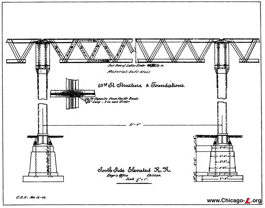
(Drawing from Graham Garfield collection)
The original design of the Jackson Park branch suffered from the decision to "hang" the stringers from the cross girders. You first erect the columns and cross girders and then "drop" the stringer onto the supporting structure. The bottom flange of the stringer is not connected in any way to the cross girder. The top flanges act in compression (think of pushing against both ends of the top flanges) and the bottom flanges act in tension (think of pulling on both end of the bottom flanges) and together the built-up stringer is sized to provide the necessary cross-sectional area to support train loads (think of it as a mini truss bridge only on its back). Having only the top flange resting on the cross girder, while cheap to construct, was ultimately a fatal flaw since all the train loading passes through that little angle. It is not know why the SSRT chose this design for the Jackson Park branch—perhaps they were trying to save time or money in their race to construct the extension in time for the World's Fair, or maybe they felt it was truly temporary and designed it as such.
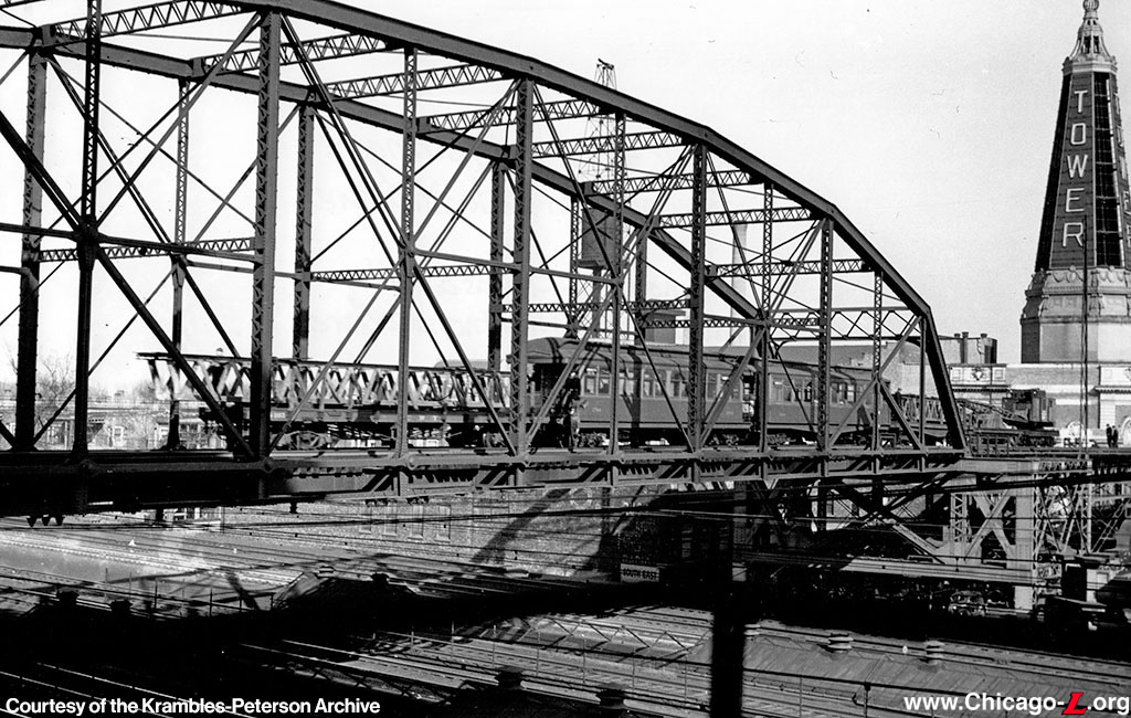
George Krambles started with the CRT in 1937 and recalled that already by that time, CRT was having issues with the unique structure on the Jackson Park Branch. His 1937 photo shows a work train crossing the pin-connected truss bridge (over the IC) carrying new stringer sections to be installed.
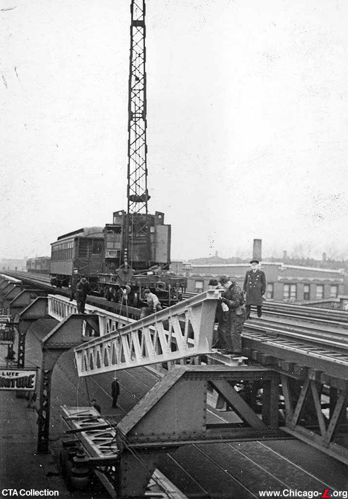
Here, new stringer sections are being lifted into place on the Jackson Park "L" structure over East 63rd Street. But "new" stringers repeated the same design flaw. The engineers at CRT may have thought that because they were using steel rather than "best iron", the structure would last. It did not.
CRT and later CTA both experienced a high rate of fracture of the original connections. To try and rectify this, there were two more rehabilitation projects on the Jackson Park branch structure during the CTA era.
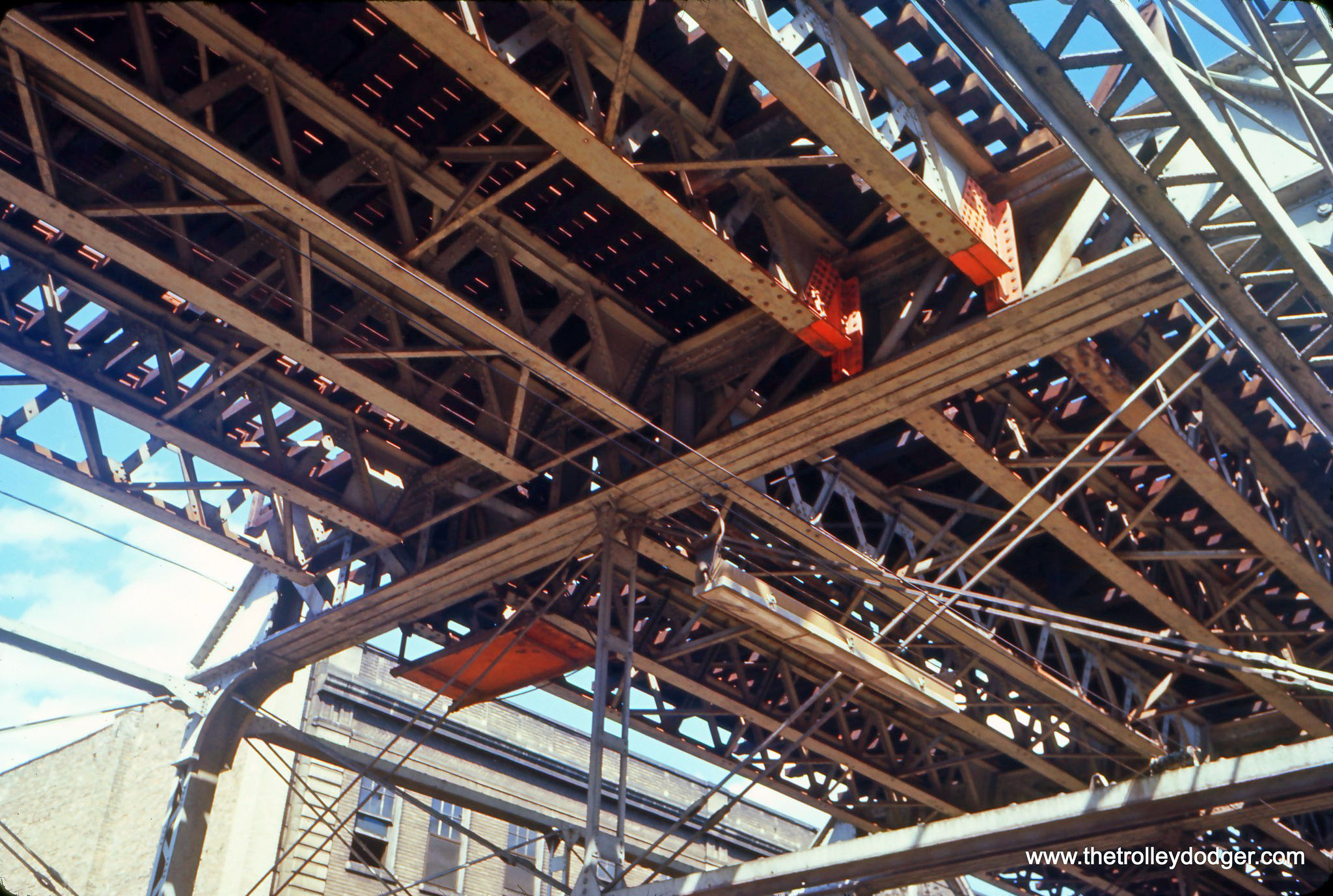
(Photo by William C. Hoffman, courtesy of The Trolley Dodger)
The first project in the 1960s was to retrofit the stringer end by welding a plate at the ends of the open web truss and connecting it to the face of the cross girder. This William Hoffman photo from September 5, 1966 shows some of these new connections in place at Blackstone Avenue, their orange primer helpfully highlighting them against the existing butterscotch-painted steel. The rehab in the 1980s replaced the open webbed cross girders with solid cross girders for better rigidity (everywhere except at the stations, since that same work at those locations would have been an order of magnitude more complicated to perform). They also rebuilt many of the column bases at the same time. Collectively, these two projects seem to have finally stabilized the Jackson Park "L" structure.
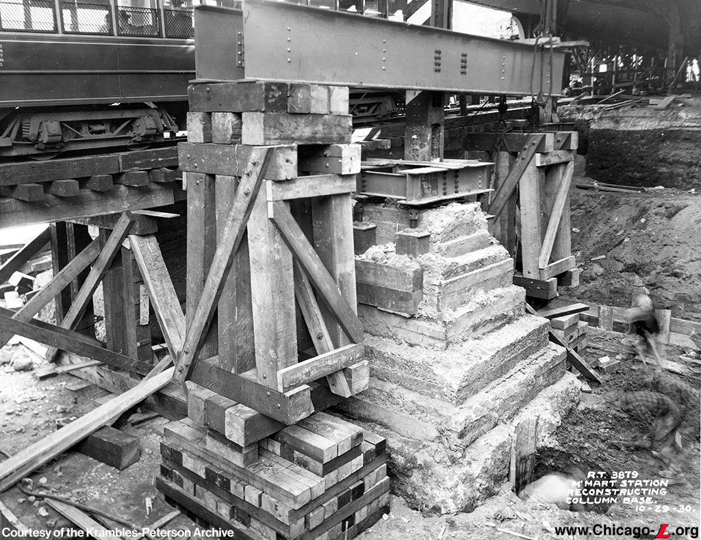
A typical column footing for the "L" was exposed during the construction of the Merchandise Mart station during 1930. You can immediately see why it was referred to as a wedding cake design.
A major issue for CTA in the 1990s was the "pumping" of the column footings. In this instance, the top of the foundation deteriorates, leading to loss of support for the column base, as well as inducing a twisting motion into the cross-girder. As an aside, the column base in this photo was just 30 years old at the time and already shows evidence of deterioration.
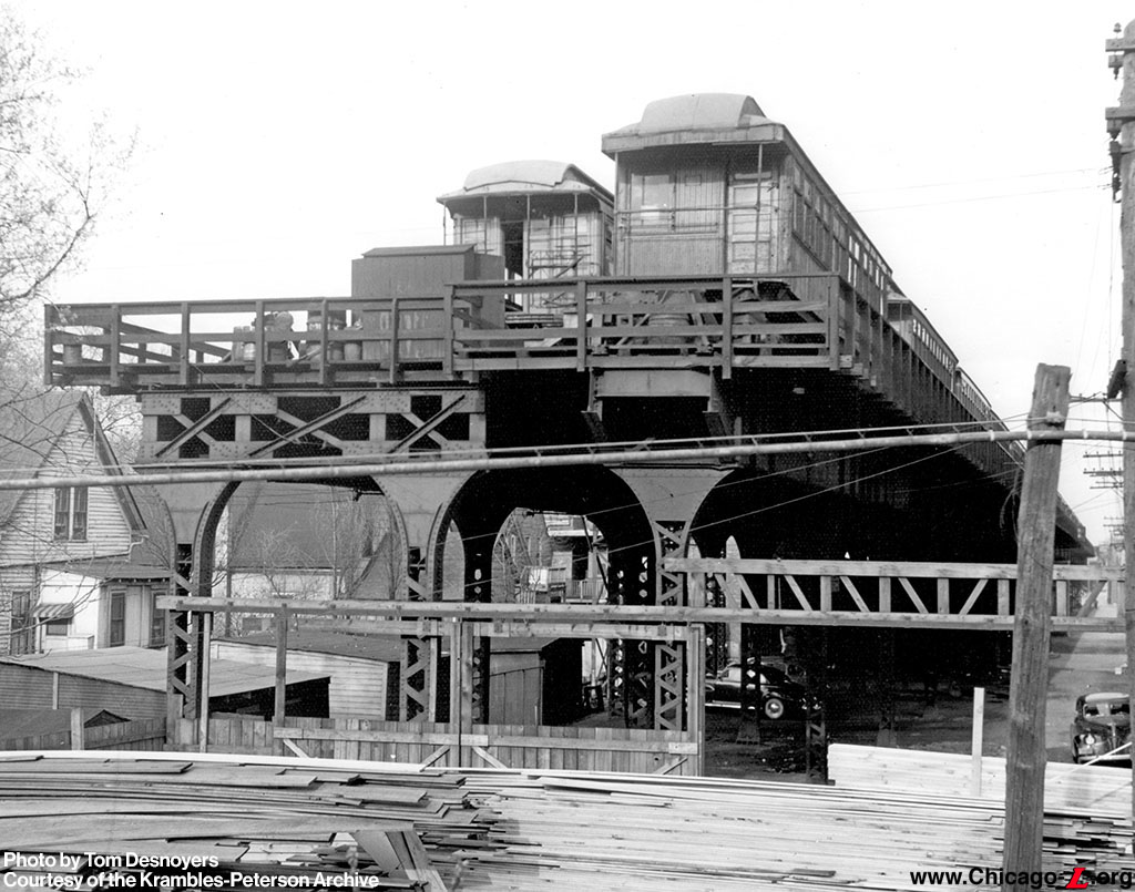
Moving to the Metropolitan, the end of the Humboldt Park structure at the Lawndale Terminal is shown in this April 28, 1952 view by Tom Desnoyers. The structure supporting the two running tracks to the north (left) of the view uses an open cross-braced cross-girder header, which was unique to the Met. This style of cross-girder could also be found on portions of the Met Mainline structure. The single lay-up track to the south (right) is not braced to the other two. This may be since the track was used only for car storage. In concept, it is similar to the structure that was used for the Greenwich Street, New York elevated line, mentioned at the start of this piece.
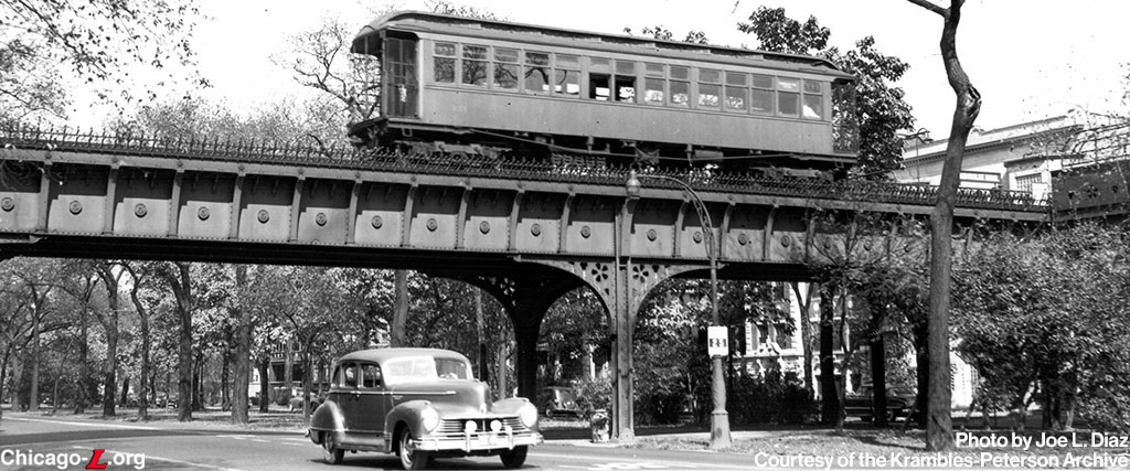
When crossing the Boulevards, extra design attention was required. Here CTA 331 heads across Humboldt Blvd. circa 1948 in this photo by JL Diaz. All the extra frills on the structure are just that, though they definitely add to the charm of the structure. The columns are of interest, as they are solid I-shapes, as opposed to open web design. This may have allowed the designer to eliminate [unsightly] bracing otherwise required to absorb the longitudinal loads.
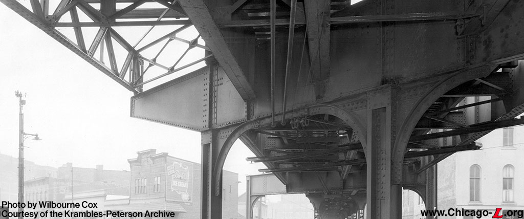
Wllbourne Cox focused on the Met structure at Ogden on the Garfield Park branch in this 1947 view. The columns are again solid I-shapes (as in the Humboldt Blvd. photo). The cross-girders are also solid built up beams, as opposed to the open cross-braced cross-girder header seen in the Lawndale Avenue shot. The Met employed this construction on the many skewed angle street crossings they had (think Milwaukee Avenue out to Logan Square)). The angled crossing of the rail line and the street results in some unusual loadings that the designers had to account for.
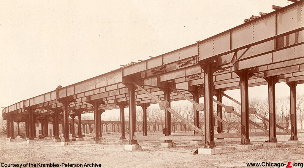
The Northwestern Elevated (NWE) structure is shown looking west-northwest past the future site of the Sheridan station on April 2, 1897. The last of the four "L" divisions to be constructed, the NWE had the advantage of learning from the experiences of the others, as well as having one of the best engineers of the day as its Chief Structural – JAL Waddell. In private practice since 1887, Mr. Waddell set standards for elevated railroad structures throughout the country. Author Stan Kaderbek worked as a structural engineer for CTA in the 1970s and 80s and he noted that the North Side "L" structure did not suffer many of the problems that plagued the other divisions. Those issues included: cracked connection angles; dodgy stringer end connections; and, issues with stringer support. Note that all the stringers are solid steel, as opposed to the open web design used on some of the older portions of the system.
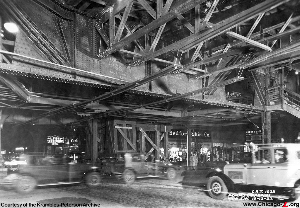
This superbly-lit view was taken at Adams and Wabash on October 12, 1927. It clearly shows the open web type stringers with full connections to the crossgirder and parallel to the trackway and the intersection with the cross girder making up the end of the station mezzanine. The trolley troughs to carry the CSL wire under the mezzanine are also visible.
There are some interesting variations in the Loop structure. Not every station was built with a mezzanine, and on the Van Buren leg, the columns were located along the curbline, unlike the practice on the other three sides of the Loop. The alignment along Wabash was the second of the Loop segments to open on November 8, 1896.
The authors acknowledge William D. Middleton's 2003 book "Metropolitan Railways," as well as Bruce Moffat's 1995 CERA Bulletin "The Development of Chicago's Rapid Transit System, 1888-1932." Both references provided valuable information on the "L" structure, as well as the developments that preceded it.
|
|
|
