|
|



|
|
|


.
On the Matter of "L" Interlockings:
Appreciating its Signals and Towers
By Kendrick Bisset and Art Peterson
All photos from the Krambles-Peterson Archive
|
|
|
|
|
.
On the Matter of "L" Interlockings:
Appreciating its Signals and Towers
By Kendrick Bisset and Art Peterson
All photos from the Krambles-Peterson Archive
Why Have Interlockings?
Keeping trains safely separated from one another is essential to the operation of a densely-trafficked line or network of lines. As early as 1834, the Liverpool & Manchester Railway was using manually-operated, fixed-signaling devices. The first installation of a centralized, lever-controlled signal installation was made on the London & Croydon in 1843.
A limitation of this first machine was that the signals and the switches remained independent of one another, meaning that conflicting routes could still be lined. It was not until June 1856 that John Saxby received a patent for a mechanical mechanism, one where the signals and switch points were interlocked. Use of the term "interlocked" means that the switch, lock and signal appliances were interconnected so that their movements must succeed each other in a pre-determined order. In 1863, Saxby would join forces with John Farmer, to form Saxby & Farmer (S&F).
In the US, the Philadelphia & Trenton (a Pennsylvania Railroad predecessor) gets credit for installing the first interlocking on December 7, 1870. George Westinghouse formed Union Switch & Signal (US&S) on May 1, 1880. He acquired patent rights to produce interlockings conforming to the designs of several other companies (including S&F). From 1891, US&S developed the electro-pneumatic (EP) interlocking and by 1900, there were 54 of these interlockings in use across the United States.
Early "L" Interlockings
There are no surviving records on what was initially installed for the interlocking plants on the various "L" lines, save for what the Metropolitan West Side Elevated (MWSE) filed in 1900 with the Railroad & Warehouse Commission of Illinois. It's unknown why the other component companies did not similarly report to the commission. Even the MWSE's listing appears to be truncated, including information on only five locations, with four of those being along the Met mainline. That 1900 listing shows all five plants to have been National Signal mechanical installations. The permits for these plants were issued by the commission between 1895 and 1897. Regarding National Signal, this had been an independent company from 1895 until 1898, when it became a part of US&S.
Throughout the Chicago Elevated Railroads (CER) and Chicago Rapid Transit (CRT) eras, there continued to be a fascinating variety of interlocking plants in service. "Exotic" locations like Stewart Junction (where the Normal Park branch took off from the Englewood) or Lower Wilson Avenue still had manned interlockings, though not all of these were staffed 24 hours per day, seven days per week. This piece celebrates some of those unique locations/operations as they then were.
Four Fascinating "L" Interlockings
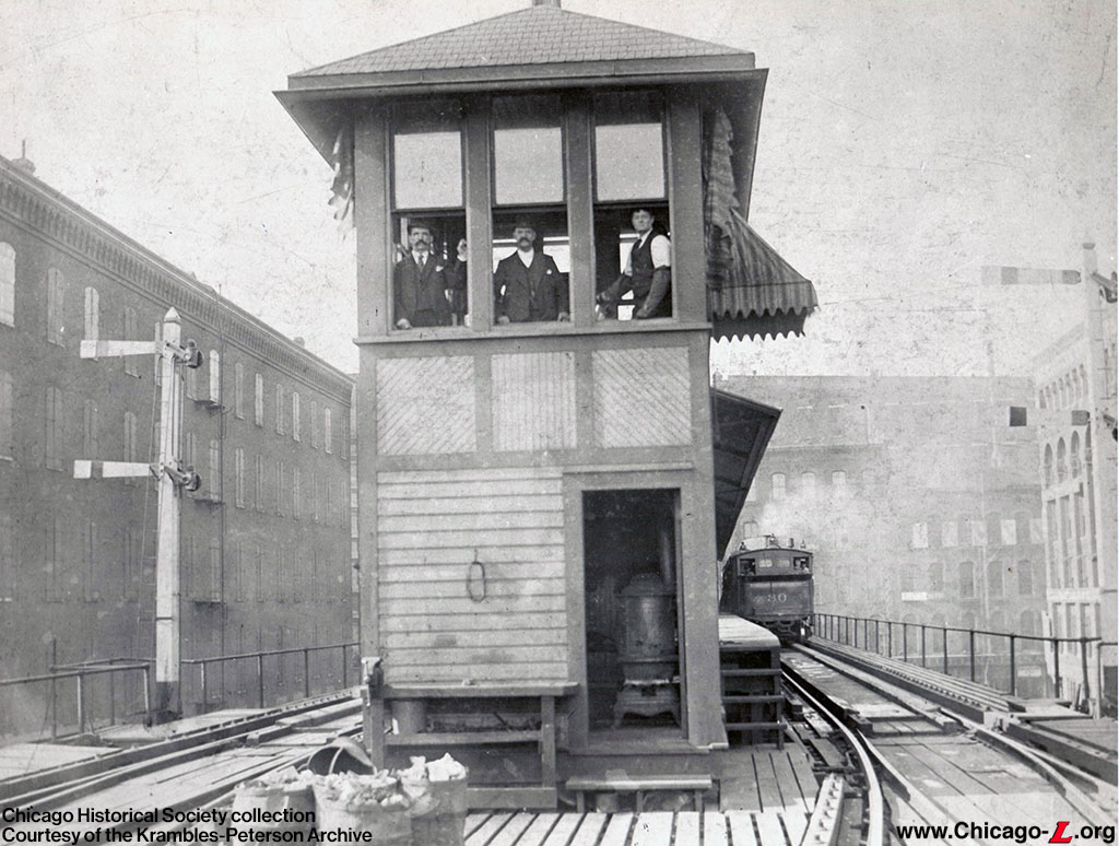
All eyes are on the photographer in this view of the Market/Madison Tower, circa 1895. The tower was located at the north end of the Market Street terminal and would remain there until operation of the stub closed in 1948.
Lake Street Elevated (LSE) trains began serving this terminal from November 4, 1893. The original terminal became a branch with the extension of the "L" east to State/Lake on September 22, 1895. Locomotive 30, to the right, was built by Baldwin during December 1894. With the tower windows open and one man working in shirtsleeves, this view could not have been taken before 1895. Note the tall semaphore signals; nearly all the later installations used so-called "dwarf" signals, much lower and narrower. This view is from the Chicago Historical Society's collection.
A 1945 inventory of interlockings shows that Market tower was then equipped with a Johnson Signal-designed interlocking. Johnson had been an independent company between 1888 and 1892, when it was sold to Hall Signal. In 1895, Hall was sold to National and ended up in the US&S fold from 1898. US&S sold machines pursuant to these patents until at least 1909. The machine at Market was equipped with 16 levers and controlled seven signals. This was the only machine then in use on the CRT which conformed to the Johnson Signal interlocking machine design.
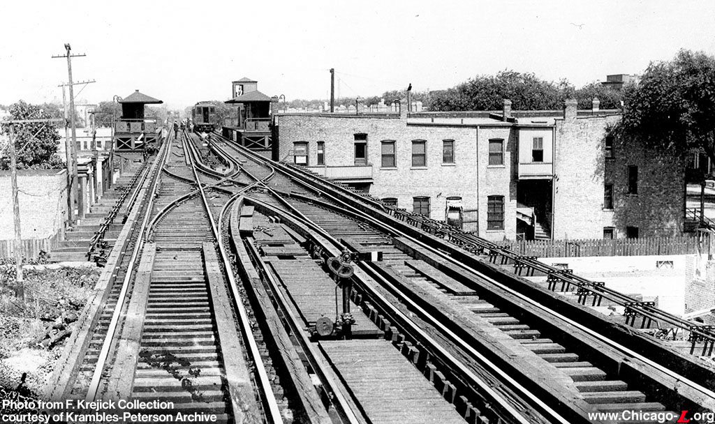
St. Louis on the Garfield Park branch, was placed in service in 1911, per the information that Bruce Moffat included in Shore Line's Dispatch 1.
This view looks east to the station, circa 1911. The pipes running to the right of the eastbound (right) track and to the left of the westbound (left) track indicate this is a mechanical plant, one where the levers in the tower will be tall to ensure the towerman can apply sufficient force to move the equipment. These pipes would move longitudinally resulting in the movement of the field equipment (signal, switch, etc.). The signal in the foreground is of the "dwarf" style made by US&S around that time, and was the kind used throughout the system at this time. Sharp-eyed readers will note an early form of slow zone marking on the eastbound track clear of the diamond crossover.
The 1945 interlocking inventory recorded that the machine at St. Louis was built according to the National Signal patents by US&S. The tower was then staffed 12 hours per day, to allow expresses ("L" and CA&E) to overtake local trains. The plant at St. Louis included 16 levers (eight with detector bars), twelve signals and four trip stops. There were seven interlocking machines then in use on the CRT which followed the design patents of the National Signal interlocking machines.
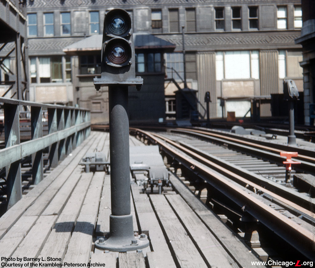
On July 14, 1950, the photographer looked west out of the North Water Stub towards the tower and the Merchandise Mart forming the backdrop. This home signal (on the south track of the stub) was a two-aspect signal (mirroring what was then common on many of the "L" semaphores), showing only "stop" or "proceed" indications. Here, it is displaying a "stop" signal, though that's barely visible. Note the "rooster tail" type center trip to the right, which is in the "trip" (up) position. As was common with these trips, the side that would potentially be hit by a train was painted red-orange. The other side of the trip (when down) would have been painted white.
The signal and the interlocking machine in the tower were system uniques on the CTA -- they were both provided by General Railway Signal. This plant was fully electric, as opposed to electro-pneumatic. The North Water machine was equipped with 23 levers, eight of them having detector bars. A detector bar was a mechanical device used to keep a switch locked in position while a train was on the switch. This technology was superseded by detector locking, where track circuits were used to lock the switch. The plant also included 15 signals and seven trip stops. That same tower also housed a US&S EP interlocking machine, controlling the Chicago River bridge interlocking.
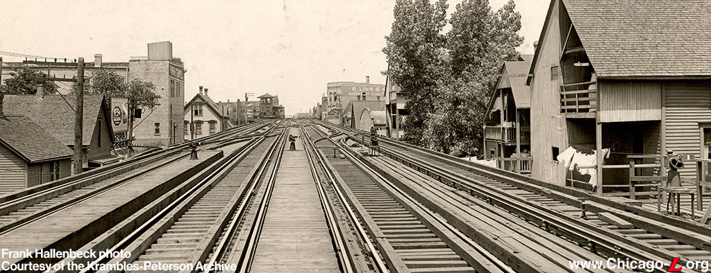
Circa 1913, Frank Hallenbeck recorded this view looking north towards the Clark Junction tower. The view was included in US&S's 1914 issue of their Bulletin 73, describing their EP interlocking product. The US&S artists felt the need to retouch the hanging laundry off to the right before including this image in their publicity materials!
US&S in that Bulletin 73 (above) noted that the EP interlocker was in use at 23 locations on the CER, with a total of 392 levers under their control. The Clark Junction installation dated to 1907 when the Ravenswood branch was opened. Note that the normal-direction signals (called "low dwarf signals" by US&S, and the typical signal used on the rapid transit) to the right of the view have center trip stops. US&S reported that the first trip stops had been used on the Boston Elevated Railway from 1900. They were also included on the Interborough Rapid Transit subway of 1904.
The US&S EP interlockers were used for nearly half of the 54 interlocking machines on the CRT. US&S noted that their EP design offered maximum safety, simplicity, reliability, flexibility and capacity. Another advantage was that the use of uniform air pressure throughout the plant allowed for uniformity of equipment. Clark Junction was equipped with 22 levers (12 equipped with detector bars), controlled 20 signals and six trip stops.
The authors acknowledge Bruce Moffat's 1995 CERA Bulletin, The 'L': The Development of Chicago's Rapid Transit System, 1888-1932 and his 2006 Shore Line Interurban Historical Society Dispatch 1, Cooperation Moves the Public. Ben Feely provided access to US&S Bulletin 73, which was essential to the preparation of this piece. Information on the development of railway interlockings came from the "Trains" magazine site.
|
|
|
