|
|



|
|
|


.
Trip Stop Story, Part 1:
Migratory Patterns of "L" Track Trips
By Kendrick Bisset and Art Peterson
All photos from the Krambles-Peterson Archive
|
|
|
|
|
.
Trip Stop Story, Part 1:
Migratory Patterns of "L" Track Trips
By Kendrick Bisset and Art Peterson
All photos from the Krambles-Peterson Archive
In its Bulletin 73 (of 1914), Union Switch & Signal (US&S) reported that the first installation of automatic track trips (which would stop a train if it passed a red signal by causing an emergency brake application) had taken place on the Boston Elevated Railway in 1900. Another vote of confidence for this technology could be found in the New York City IRT subway of 1904, which also deployed automatic track trips.
The four primary "L" companies, as well as the Chicago Elevated Railways (CER), adopted this technology in Chicago. From a review of the four component companies' car photos, it appears the Northwestern Elevated (NWE) was the first to adopt this technology, around the time the Ravenswood branch was added to its network from May 18, 1907.
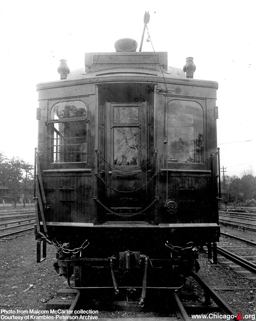
This photo from the Malcom McCarter collection shows one of the NWE 769-class motor cars shortly after delivery from Pullman in early 1909. The air valve and cock handle can be seen below the coupler and between the air hoses on the approximate centerline of the car.
Eventually, all motor and control trailer cars in the CER (later, Chicago Rapid Transit [CRT]) fleet would be equipped with a variation of this safety installation.
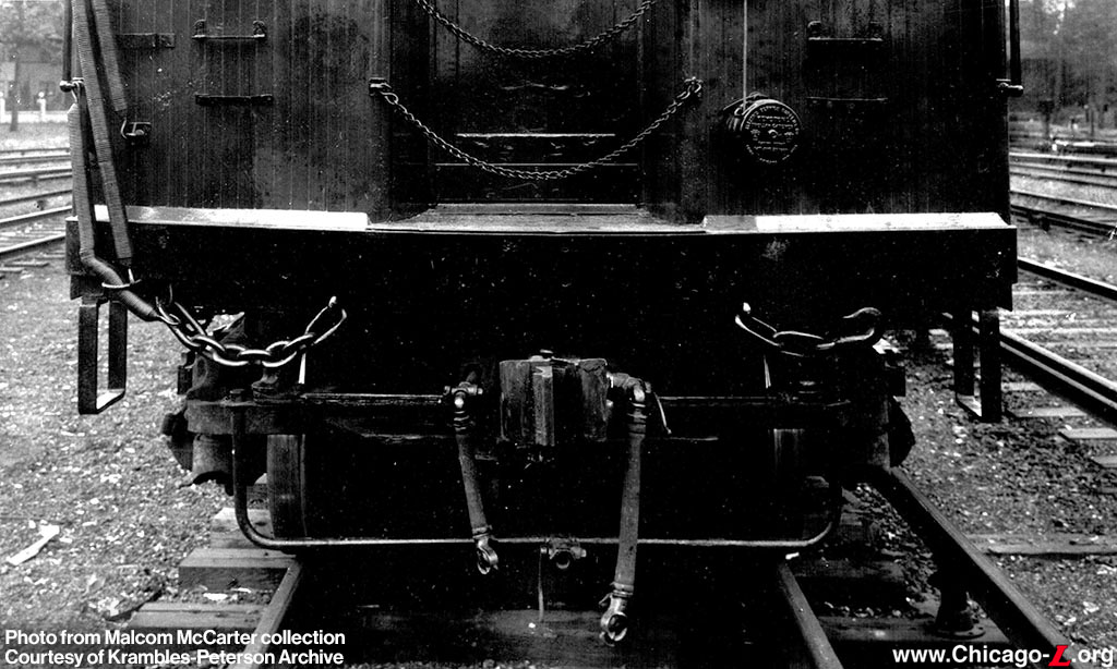
A close-up view of the area under the NWE 769-class car's anticlimber provides a touch more detail on the installation used to equip these cars with the air-operated center trip device. Below the air valve, one can see the trip cock handle extending further down, which would cause the train's emergency brakes to apply if a signal were passed displaying a "stop" indication, due to collision with the wayside trip.
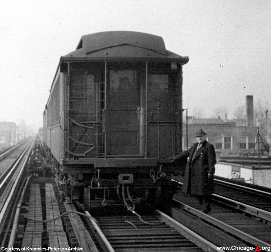
Other Duties as Assigned: the presence of that air valve at the ends of the motor and control trailer cars made it easier for CRT to use this equipment to support other needs. Here, a train of 181-class cars has air hoses connected to support the work of a structural repair gang on the Jackson Park branch circa 1937.
Sadly, both the photographer's name, as well as that of the CRT man posing next to these cars, are lost to history.
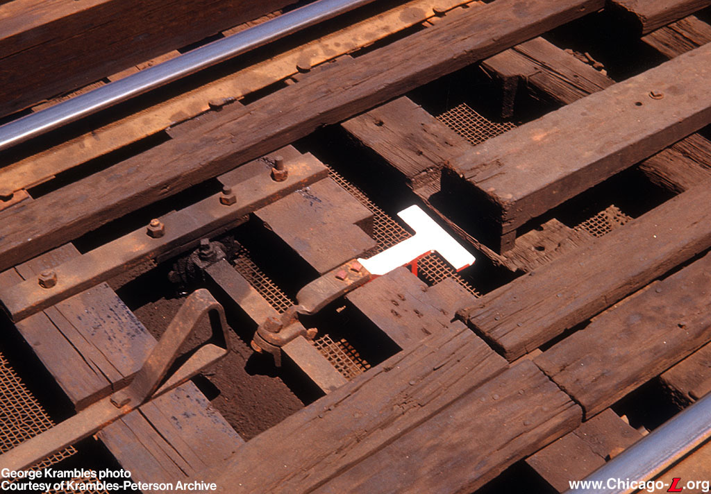
Although the center trip arrangement worked to CER/CRT's general satisfaction, there were some disadvantages with it. The profile of multiple ties had to be altered (as shown here at Pulaski/Lake on May 29, 1950) to ensure that a lowered trip lay horizontally out of the path of passing trains. In addition, a few ties on approach (to the right of this view) had to be milled to accommodate the approach-side (normal direction of train travel) incline piece. These items had to lay below the trip cock of a train which approached a signal that could be safely passed.
With the center trips, CRT/Chicago Transit Authority (CTA) practice was to paint the departure side of the trip white, while the approach side of the trip was painted a red-orange color.
Another fundamental disadvantage with the center trips (some called the wayside trip design a "rooster tail") was that when up, the wayside trip arm extended high enough to engage other undercar equipment, including the traction motor cases. This meant that at a minimum, the wayside trip arm would be knocked out of alignment, if not mangled, by the collision with the passing train.
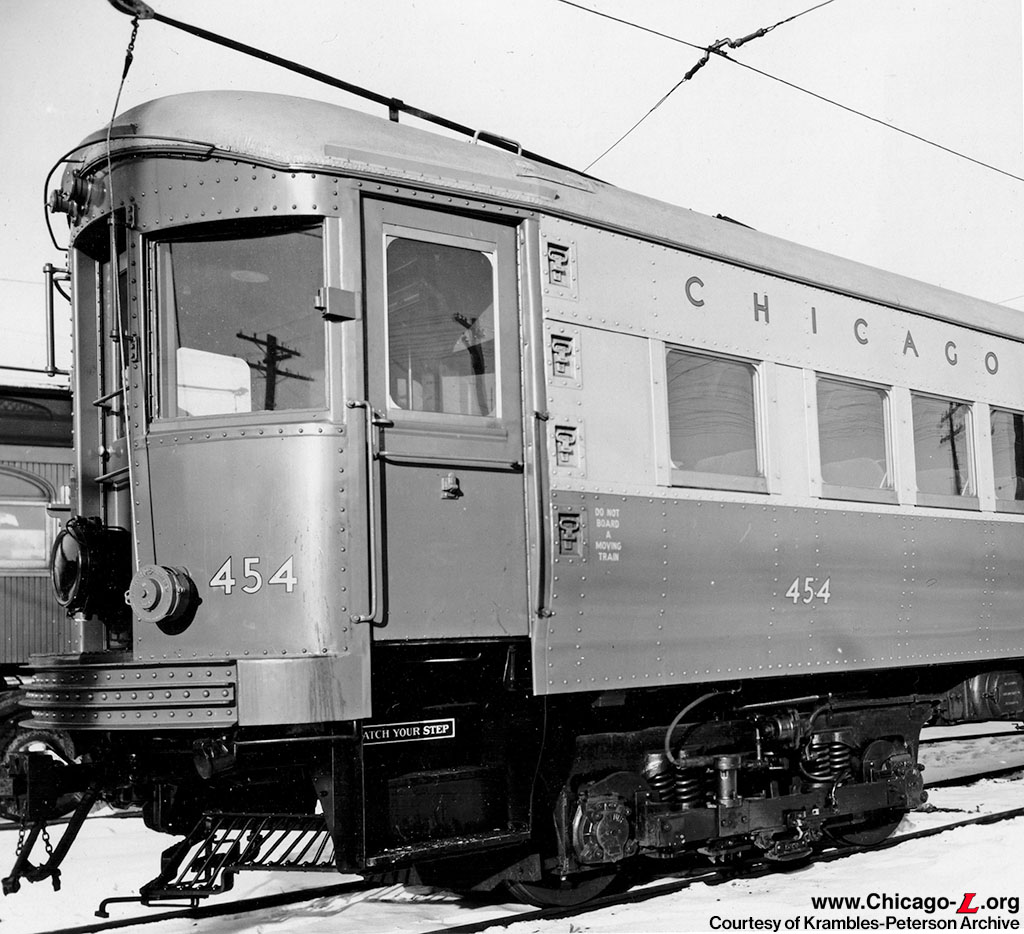
To ensure safety of all operations on the "L" was assured, the tenants also had to equip their cars with center trips. The fresh snow under the pilot of this newly-delivered Chicago Aurora & Elgin (CA&E) St. Louis-built car helps to show the track trip arrangement this road used. The trip itself was located behind the pilot (on those cars with them). What's visible in this view is the trip arm, which extended out in front of the pilot. This arm extended back to the trip cock handle.
With the trip extending out in front of and below the pilot, you can see how potential mis-alignment of the pilot had the potential to cause a lot of trouble by resulting in unnecessary tripping of a train.
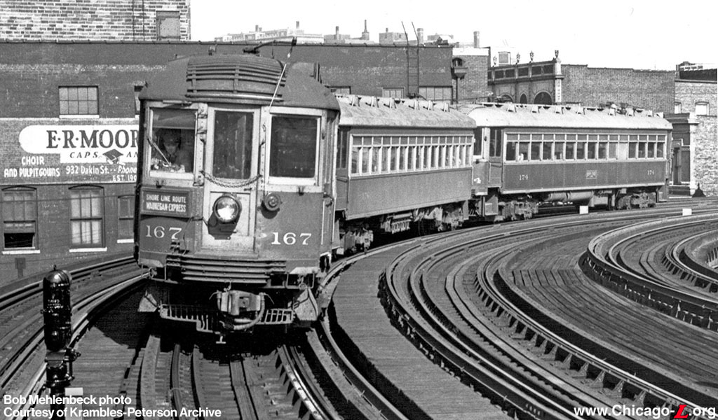
Similarly, North Shore Line (NSL) cars had center trip equipment, as shown in Bob Mehlenbeck's 1947 view of a northbound train approaching the Sheridan station. The carborne device is visible immediately below the coupler/pilot.
Air valves were used to vent the brake line (similar to what one would have found on the brake stand or the passenger emergency equipment).
As it happens, both the CA&E and NSL photos included with this piece post-dated a major shift in the CRT's approach to the location of the track trips. But that's a story for another installment to address.
The authors acknowledge Bruce Moffat's 1995 CERA Bulletin, The 'L': The Development of Chicago's Rapid Transit System, 1888-1932. Ben Feely provided access to US&S Bulletin 73, which was essential to the preparation of this piece. Walter Keevil also provided information on the arrangements used on the CA&E and NSL cars.
|
|
|
