.
Traction Power
.
Substations | Third Rail and Trolley Shoes
Generally speaking, the electricity that powers the "L" comes from the local power utility -- in the case of the Chicago area, that is Commonwealth Edison or "ComEd" -- after being converted at substations along the lines. Raw alternating current (AC) is bought from ComEd and fed to about 50 substations spread along the eight "L" lines. At the substations, it is changed from alternating current to 600 volts direct current (DC) and fed, via duct banks and hundreds of miles of heavy traction power cables, to the third rail along the tracks. Every railcar has four third rail "shoes" (one on each set of wheels), which pick up the 600v DC from the third rail and feed it to the traction motors that power the train.
The amount of power drawn by the system is largely a function of the distance covered by a particular line, how many trains (and how many cars in each train) are running on the line at that moment, and how much power those trains are drawing (i.e. how fast they're going, etc.). Trains draw different amounts of power depending on their operational needs, and draw less power at lower speeds and when they are not as heavily loaded (and thus are a little lighter).
Substations
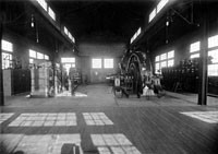
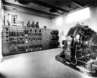
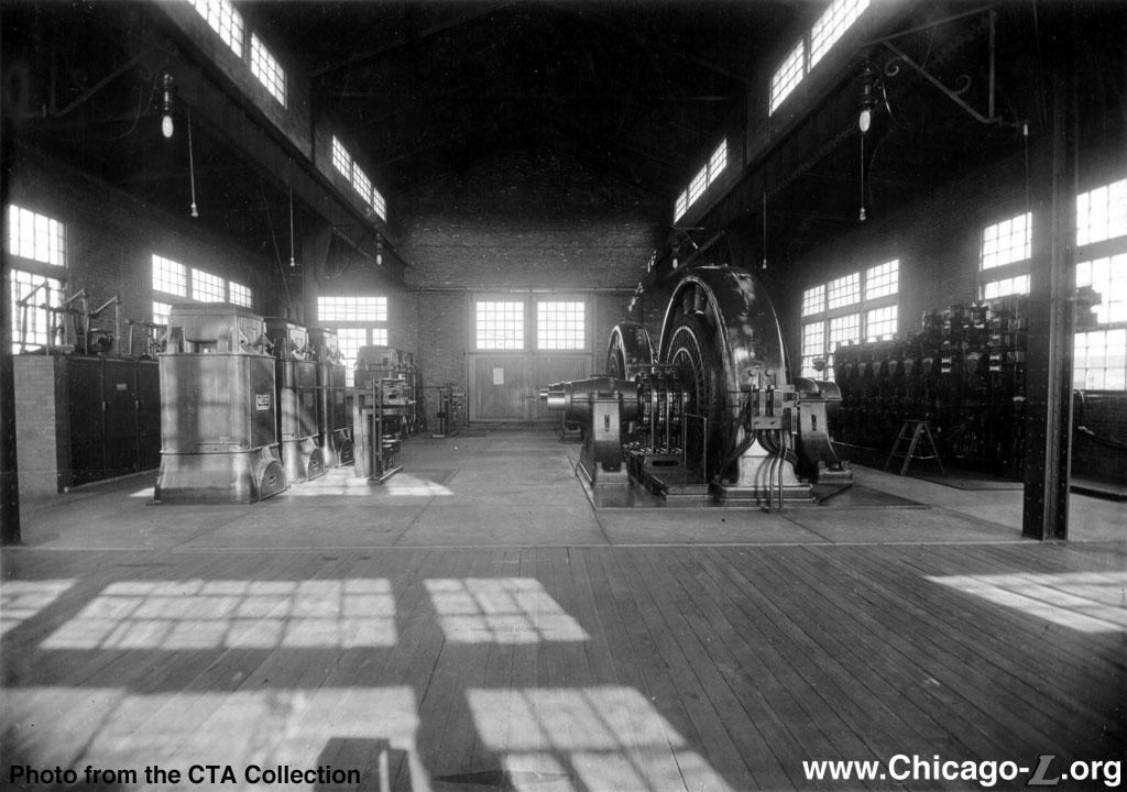
The interior of Calvary Substation on the Evanston branch is seen in 1914. For a larger view, click here. (Photo from the CTA Collection) |
Substations spread along the "L" lines are used to convert, or "rectify", three-phase 50Hz or 60Hz alternating current (AC) into direct current (DC) from ComEd, the local power utility, to power the trains. Although this general setup has not changed since the first electrically-powered "L" route, the Metropolitan West Side Elevated, opened in 1895, the technology for performing the conversion and other specifics has developed as technology has advanced.
Originally, the conversion equipment usually consisted of rotary converters. A rotary converter is a type of electrical device which rectifies the power from AC to DC mechanically. In the late 19th and early 20th century, rotary converters were commonly used to provide DC power for commercial, industrial and railway electrification from an AC power source before the advent of chemical or solid state power rectification.
A rotary converter is a large, rotating electromechanical device, like a motor or a generator. Not simply a motor or a generator, or even a pairing of each, the rotary converter is actually both at once, a hybrid of an AC motor and a DC generator (dynamo). Unlike a motor, it turns no load, and unlike a generator, it is turned by no engine -- it just sits there and turns, its own load and engine, producing DC power, along with a lot of noise, heat, and dust in the process.1
In the mid-1920s and '30s, mercury arc rectifiers began to replace the rotary converters. A mercury arc rectifier is an electrical rectifier, and is a type of cold cathode gas discharge tube but is unusual in that the cathode, instead of being solid, is made from liquid mercury and is therefore self-restoring. As a result, mercury-arc valves were more efficient than rotary converters, being much more rugged, long-lasting and could carry much higher currents than most other types of gas discharge tube. Mercury arc rectifiers were the primary method of rectification before the advent of semiconductor rectifiers such as diodes, thyristors and gate turn-off thyristors (GTOs) in the mid-20th century.2
Compared to the rotary converter, mercury arc and semiconductor rectifiers did not need daily maintenance, manual synchronizing for parallel operation, skilled personnel and they provided clean DC power. This enabled new substations to be unstaffed, only requiring periodic visits from a technician for inspection and maintenance.3
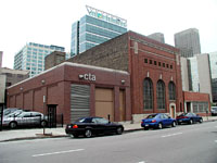
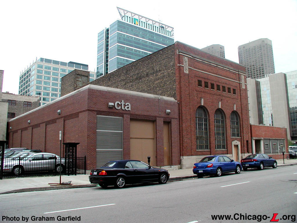
The new and old Haymarket Substations are seen looking southeast on May 7, 2004. Serving the Lake Street 'L' and located a few blocks south, the original substation building is on the right. It was replaced by the smaller building on the left, housing modern power inversion equipment. The original building was subsequently used for storage. For a larger view, click here. (Photo by Graham Garfield) |
An article in the April 1980 CTA Transit News company newsletter described the design and operation of modern "L" substations (it was specifically describing the then-new Kolmar Substation, but the description generally applies to all modern CTA substations):
All of the new CTA substations are designed with economy a priority. They need no personnel except for a maintenance check once a week.
At the substations, 12,000 volts of AC current from the electric company are channeled into two giant transformers which reduce the voltage to 600. The transformers are in an open-air courtyard. Since they get very hot, they must be chemically cooled in the summertime. The cooling system is included in the transformer itself.
Once the voltage is reduced, the current must be converted from AC type to DC type. This work is done by machines in the main room of the substation called rectifiers. This conversion is done because the third rail only accepts DC type electricity.
In the case of a power failure, Commonwealth Edison has provided an emergency power supply that switches into service automatically and lasts until the normal power supply is restored.
With all of this power going in and out of the station, [substations have] plenty of circuit breakers and trips to prevent overheating of the cables. Even the circuit breakers have circuit breakers--called reactors. The reactors are located in the basement of the substation. Loud crashing sounds heard periodically are the result of the reactors absorbing gear switches that would be too much for the more delicate circuit breakers to handle.
Also in the basement is the grounding system for the transformers. All of the cables carrying the 12,000 volts of power to the substation are encased in concrete for safety purposes and in compliance with the electrical code.
The delicacy and precision of the equipment in the ... substation requires clean, pure air. To accomplish this, large air filters [are] installed. The filters attract and capture dust and dirt particles in the substation.
Every switch at the substation is remotely monitored and controlled from the Control Center... For example, emergencies or irregularities on the tracks requiring isolated power shut-offs are handled through the substation by the power supervisor at the Control Center. No one has to run to the substation to pull switches or push buttons.4
According to CTA, a typical substation includes two conversion systems to provide redundancy. The optimal distance between substations on the "L" is approximately two miles, dependent on loads.5 There are currently approximately 50 substations around the "L" system.
Third Rail and Trolley Shoes
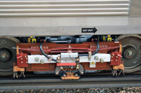
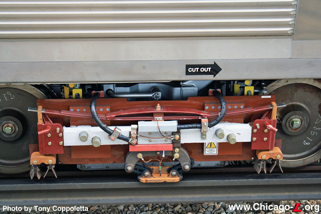
The gravity third rail shoe and sleet scraper are seen on the fresh, clean trolley block on brand-new car 5011 on October 6, 2009. For a larger view, click here. (Photo by Tony Coppoletta) |
Third rail systems are a means of providing electric traction power to trains, and use an additional rail (called a "conductor rail", "trolley rail", or simply the "third rail") for the purpose. On most systems, the conductor rail is placed on the ends of the track ties outside the running rails (the rails the train wheels rest on) -- the "L" uses this placement -- but in some cases a central conductor rail placed between the running rails is used. The conductor rail is supported on ceramic insulators or insulated brackets, typically at intervals of 10 feet or so.
The conductor rail is usually made of high conductivity steel, and the running rails have to be electrically connected using wire bonds or other devices, to minimize resistance in the electric circuit. On rail systems where the traction power is transmitted through rails, there has to be a positively-charged rail and a rail for the negative return. In some systems, there are two separate rails besides the running rails for this purpose, one positively charged and one negatively charged. On other systems, like the "L", the third rail carries the positive charge, and the negative return is sent through one of the running rails.
The electric current is transmitted from the conductor rail to the train's motors and power systems through metal contact blocks called "third rail shoes" or "trolley shoes" (or, often, simply "shoes") which make contact with the conductor rail. The shoes slide along the top of the conductor rail, with power transmitted by their physical contact.
The conductor rails have to be interrupted at level track crossings, at crossovers and switches, and at grade crossings with streets, and ramps are provided at the ends of the conductor rails sections to give a smooth transition to the train shoes.
History and Development
There are several different ways that trolly shoes can be designed to contact the third rail, each with its own advantages and disadvantages. This passage from a 1916 edition of Electric Railway Journal describes some of the common methods:
Third rail construction were roughly classified... as the overrunning, the underrunning, and the side contact types of which typical installations.... The early installations were of the overrunning contact type, a gravity shoe being used. Later it became necessary to provide protection for the rail, and the gravity shoe was no longer practical owing to the fact that the entrance to the contact surface had to be made from the side. A slipper shoe, held in contact with the rail by means of a spring, has taken the place of the gravity shoe on protected third rail systems. The protection of the overrunning third rail consists in a plank about 6 in. wide which is supported above the rail by means of brackets bolted to the ties. The underrunning type can be protected both on the top and sides and this construction has the added advantage in that the rail is self cleaning in stormy weather... but it has many disadvantages.6
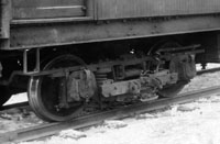
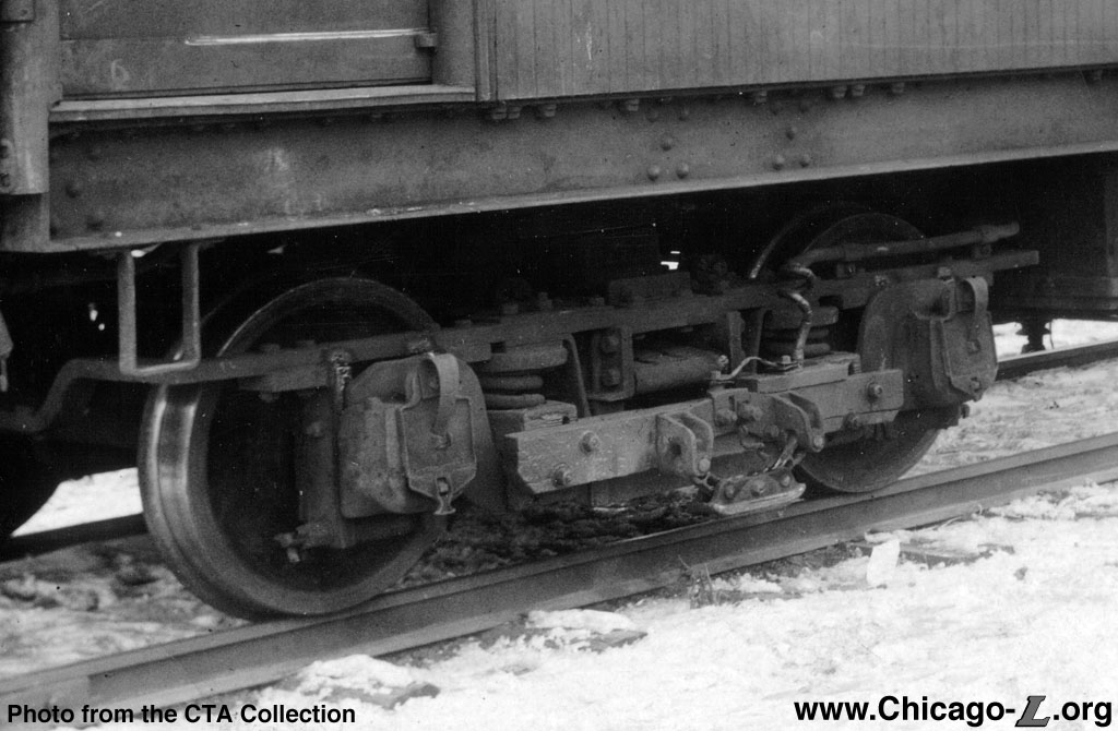
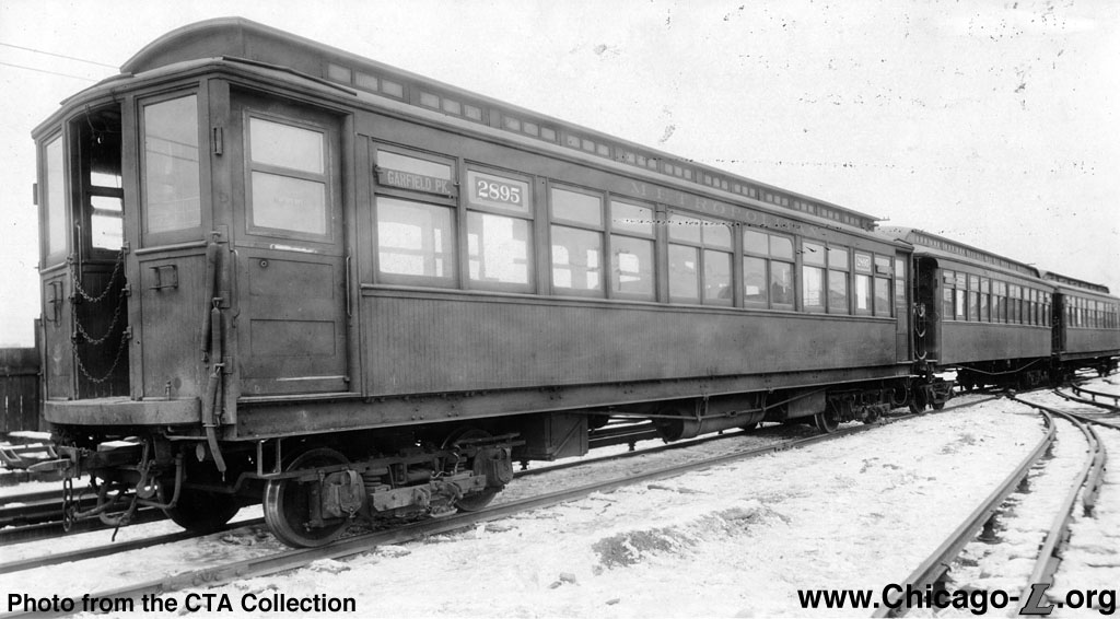
An early third rail shoe and trolley block assembly are seen on Metropolitan wood car 2895. For a larger view of the trolley block, click here. For a view of the entire car, click here. (Photo from the CTA Collection) |
The gravity third rails shoe sits directly on top of the third rail, sliding along it, the bottom of the shoe making contact with the top of the rail. As the name suggests, gravity (and the weight of the shoe, against which gravity acts) is what keeps the shoe against the rail.
At the time the Metropolitan West Side Elevated, the first "L" lines in Chicago to used electrically-powered rolling stock, was designing its electrical equipment in 1895, they looked to existing technologies that had been proven in service. The gravity third rail shoe had been developed in England in the early 1890s, and used on the Intramural Railway at the Columbian Exposition Worlds Fair in Chicago in 1893, providing the Met's backers and designers with a model they could familiarize themselves with and emulate. Seeing the successful operation of the Intramural Railway at the fair, the Met scrapped its plans for steam operation of their railroad and switched their design to electric traction, copying the Intramural's electric motor cars pulling trailers, using third rail with a gravity shoe.
When the Lake Street and South Side elevated electrified their operations in 1895-98, they too chose the gravity third rail shoe; as a result, this became the de facto standard for the "L". Although the covered third rail was later developed, the "L" never adopted this design, most likely because of the cost of retrofitting the entire railcar fleet and hundreds of miles of third rail in which there was already a significant investment in the gravity shoe model. The "L" did, however, later experiment with side paddle shoes, typical of covered third rail systems, as discussed below.
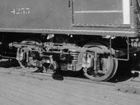
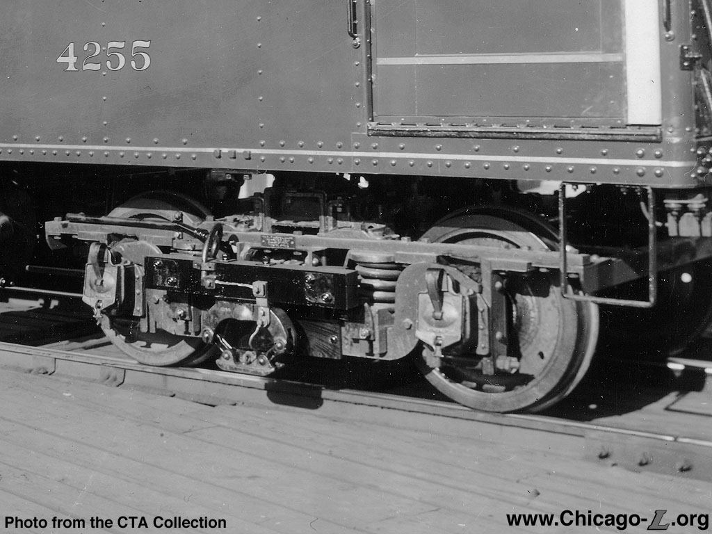
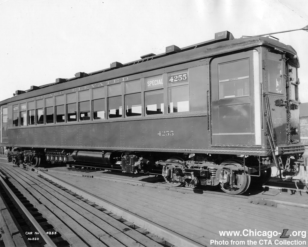
The third rail shoe and trolley block are seen on freshly-delivered car 4255. For a larger view of the trolley block, click here. For a view of the entire car, click here. (Photo from the CTA Collection) |
The trolley shoe is mounted on a beam on the outside of each truck, to assembly often referred to as the "trolley block". The beams were originally made of kiln dried clear maple and were four inches thick, and six inches high, and about four feet long -- a very solid piece of wood. By the 1970s, the beams were made of phenolic-impregnated cotton laminate and reduced in size to three inches thick by four inches high. The switch was made because the new material requires practically no maintenance, being impervious to water and needing no painting. 7
In addition to the third rail shoes, the trolley block also includes sleet scrapers, blades that hang down and run along the third rail, scraping off snow and ice (whose presence can cause the bottom of the third rail shoe to have poor contact with the third rail, resulting in arcs, insufficient conductivity, and insufficient power to the train). The blades, which are grouped in pairs and placed on both ends of the trolley block, bookending the third rail shoe, are raised and lowered by the motorman, operator, or switchman in inclement weather and raised when not needed, as their prolonged use wears down the blades quickly (and is rather noisy!). Today, the blades are typically removed in the warmer months and reinstalled each winter.
Sleet scrapers were added to the trolley block assembly at an early date. Originally, one of the sets of blades was a roller-crusher to break up the ice so the blades could scrap it off the rail. The rollers were changed to a second set of blades in the 1930s and the whole sleet scraping mechanism was electrically connected to the third rail shoe to help carry power to the car.8
Although the gravity shoe worked well for the "L" for 60 years, in the 1950s the CTA began to experiment with using a paddle-type third rail shoe instead. However, its use had nothing to do with a potential change in third rail design. Rather, the use of the paddle shoe was the result of design requirements for certain car series.
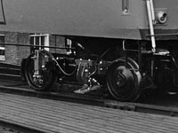
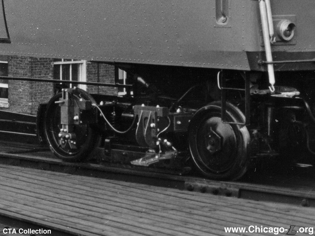
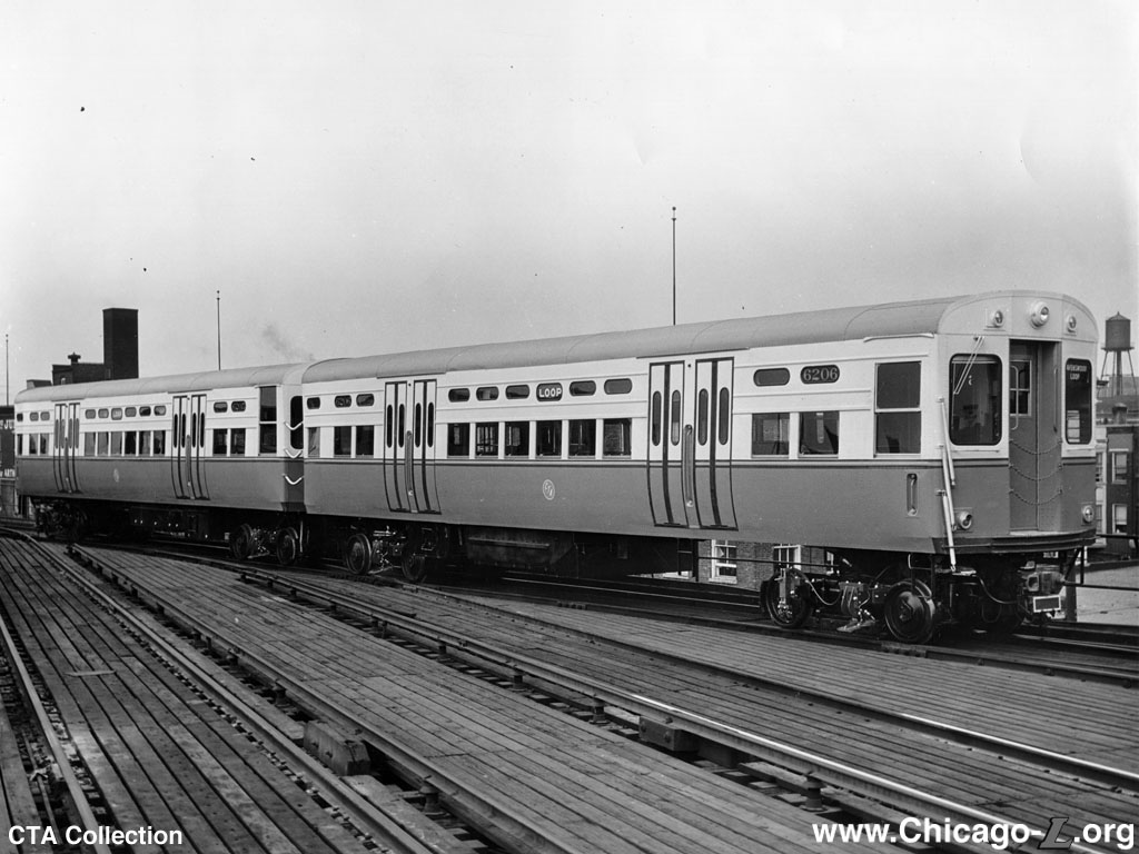
Car 6206 displays a paddle-type "flapper" shoe, part of one of the few "L" car groups not to use a gravity shoe. For a larger view of the trolley block, click here. For a view of the entire car, click here. (Photo from the CTA Collection) |
In the 1950s, the CTA was taking delivery of the 6000-series railcars, based on the PCC technology originally developed for a new generation of streetcars. The first 200 6000-series cars were built from scratch using all electric PCC technology. These cars used the B-2 truck supplied by the Clark Equipment Company, chosen because these trucks were already being used on many PCC streetcars used in Chicago (specifically, those built by the Pullman Car Company), so there was ample experience and familiarity with the design. The Clark B-2 trucks for these first 200 6000s were built new and the design was adapted for rapid transit use, which included strengthening the frame and making provision for the gravity third rail shoes. Around the same time, CTA began to replace its streetcars with buses. Not wishing to waste the investment in the relatively new PCC streetcars, the CTA approached the Pullman Co. and St. Louis Car Co. with the idea of recycling the old streetcars into new "L" cars. The original concept of rebuilding the car bodies was found to be impractical and instead new car bodies were built utilizing many of the components and much of the equipment from retired streetcars.. Thus, the remaining 6000-series cars utilized various recycled streetcar components. An integral part of this plan was the reuse of the PCC streetcars' trucks, a very expensive component whose reuse brought a great deal of cost savings to the plan. Chicago's PCC streetcars used both Clark B-2 and St. Louis Car Company B-3 trucks, and while both would eventually be recycled onto "L" cars the decision was made to scrap and recycle the Pullman-built streetcars, with their B-2 trucks, first, since there was already experience using these trucks with the 6000-series cars. In an effort to reduce truck weight and reduce stress on the truck axle assemblies, a new type of third rail shoe and sleet scraper were specified. Instead of a long beam and gravity shoe, the new design featured a short stub beam extending from the truck frame with a spring-loaded "flapper" shoe attached. Redesigned into a package, the sleet scraper was also supported on a stub beam. This design was developed so that the current collection equipment would not parallel the rubber-mounted joint of the truck torque arm and axle assembly. Shortly after entering service, the loading spring on the third rail shoe was found to be undesirable and was removed. The original thin paddle shoe was also soon changed to a thicker casting to increase its life. This design was used on cars 6201-6510. After building these 310 6000-series cars all of the Pullman PCC streetcars had been converted, so the CTA moved on to scrapping and recycling the St. Louis-built PCC streetcars. The St. Louis streetcars had B-3 trucks, which could be modified to accommodate the "L"'s standard suspended-link gravity third rail shoes and sleet scraper arrangement, so the remaining 6000s as well as the 1-50 series cars using recycled streetcar components reverted to this design.9
While returning to the gravity third rail shoe for cars 6511-6720, as well as the 1-50 series and 2000-series cars, the paddle-type third rail shoe returned in the late 1960s for the Budd-built 2200-series cars. This time, the use of this type of shoe was driven by a desire to reduce the weight of the car, using lighter components to reduce pounding on the track and to make the cars more efficient. CTA engineer Glenn Andersen had been working on developing a lighter-weight paddle shoe design suitable for use on "L" cars and, following successful test applications, it was decided to use them on the new cars. The 2200s used a new truck design -- the Budd Pioneer III -- which had two welded steel side frames held together by the axles without a conventional center bearing or king pin. CTA provided Budd with the light-weight paddle shoe design that Andersen had developed; however, Budd did not interpret the drawings correctly, and several key aspects of the design were not implemented properly. As a result, the 2200s' original as-delivered current collector/sleet scraper design proved unsatisfactory in service. The paddles did not stay on the rail at high speeds, with the air forces lifting it off the third rail when speed reached about 45mph (the cars were specified to reach 70mph), and arced badly even at slow speeds. The method of attaching the shoe and sleet scraper (like the 6201-6510 group of 6000-series cars, the 2200s had only a single scraper per package rather than two) also proved problematic, with the fiberglass mounting disintegrating quickly under stresses. Several design changes were quickly made in the attachment of the shoe and scraper to the truck frame, and a spring was added to the shoe to keep it pressed down against the third rail. Since making these modifications, the 2200s' shoe and truck design have proved satisfactory in service.10 11
Although the 2200-series cars' paddle shoe design was eventually made satisfactory in service, the CTA returned to the use of a gravity third rail shoe with the 2400-series cars in the mid-1970s. All subsequent car series have utilized a gravity shoe. With the retirement of the 2200s in 2013, all of the CTA's "L" fleet utilized gravity third rail shoes.

Sources:
- Ascher, Kate. The Works: Anatomy of a City. New York: Penguin Books, 2007.
- Keevil, Walter R. and Norman Carlson (editors), Chicago's Rapid Transit Volume II: Rolling Stock/1947-1976 (CERA Bulletin 115), Chicago: Central Electric Railfans' Association, 1976..
Notes:
1. Greenberg, Bernard S. "Rotary Converter Power Technology." nycsubway.org. 22 March 1999. Accessed 20 March 2013.
2. "Mercury-arc valve." en.wikipedia.org/wiki/Mercury-arc_valve. Accessed 20 March 2013.
3. Greenberg, ibid.
4 "New substations increase efficiency." CTA Transit News, April 1980.
5. Barry, Patrick, "CTA to begin construction on new Red Line substation near Morse." CTA Tattler blog. January 16, 2013. Accessed January 21, 2013..
6. "Sessions of the Engineering Association." Electric Railway Journal. Vol. XLVIII, No 16, 14 October 1916, p. 824.
7.
Keevil, Walter R. and Norman Carlson (editors), Chicago's Rapid Transit Volume II: Rolling Stock/1947-1976 (CERA Bulletin 115). 1976, p. 202.
8. Ibid.
9. Ibid, pp. 190 and 203.
10. Ibid, pp. 84, 190 and 203.
11. Conversation with Walter Keevil, former CTA Chief Rail Equipment Engineer, 27 March 2013.


